Orientation exercises
Orientation
In this part, you will get to know to equipment, you make your first wireing and a small program. As you go forward, the things you have to do are marked like this, with red 🤗
Happy prototyping!
Happy prototyping!
What is Arduino?
Below you can see a picture of Arduino Uno. It’s an open source based micro controller for many things to do.
There are 14 digital in/outputs, from wich 6 can be used as PWM (pulse with modulation, marked in the board with ~). Find those in the picture or from Arduino on the table.
If you want to know, what PWM means, check this 3 minutes video.
There’s also 6 analog inputs, 16 MHz oskillator, ICSP-port, a reset button, USB- and power source.
Starting to use Arduino is easy: you download and install the enviroment from internet for free (Win, Mac, Linux), you plug Arduino to PC with usb and you are ready!
Price: about 15-30 euros.
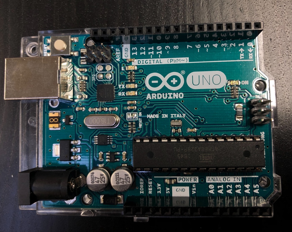
TASK: Get the Arduino board and USB-cable and plug Arduino into computer.
Breadboard
Here you can see a Breadboard. The thing with Arduino is, that you can connect lots of stuff (sensors, lights, motors etc) in Arduino. A breadboard makes it easier. You do your own circuit board, but you don’t need soldering iron.
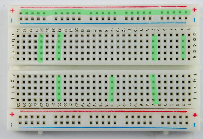
It’s important you to know wich lines are connected with each other at the breadboard. The green lines (in the picture below) indicates all lines that are connected. For example, plug +(positive) wire from Arduino into ”+line”and the whole line is now positively charged. You can pick it anywere from the line with another wire.
The center lines (a, b, c, etc.) are all connected vertically. Notice the cut in the very center: it divides the breadboard as half. The halves are not connected with each other unless you use wires.

First wiring
TASK: Get a breadboard, one resistor, one LED and two wires.
Electricat wiring is based on closed circuit. Imagine that electicity is a river that flows. It flows always to same direction. It starts from plus (positive), it goes through wire and it has to end up into ground (negative). You can use it’s power anywhere between.
With components you need to know what leg is a plus and wich is ground. In some components it’s marked clearly. If not, you can google it. In some components, it’s irrelecant. For example in LED there is no marking wich is wich. And LED lights only, if you connect it correctly. Take a look at the LED. You notice that the other leg is longer than other. The longer one is posivive. The shorter is negative (ground).

TASK: Do your first wiring as shown in the picture below.
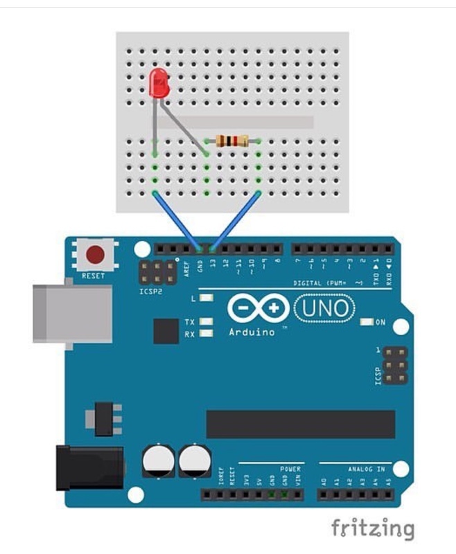
Notice from the picture:
- Plus is wired with red coloured wire, ground with black. Those are the official colour codes. Of course you can wire with any colour you like.
- From the picture you can see markings with green. It shows lines that are connected automaticly at breadboard.
What is wrong? All is done, but there is no light? Don’t worry! First you have to tell Arduino to put the light on 😇
Electricat wiring is based on closed circuit. Imagine that electicity is a river that flows. It flows always to same direction. It starts from plus (positive), it goes through wire and it has to end up into ground (negative). You can use it’s power anywhere between.
With components you need to know what leg is a plus and wich is ground. In some components it’s marked clearly. If not, you can google it. In some components, it’s irrelecant. For example in LED there is no marking wich is wich. And LED lights only, if you connect it correctly. Take a look at the LED. You notice that the other leg is longer than other. The longer one is posivive. The shorter is negative (ground).

TASK: Do your first wiring as shown in the picture below.

Notice from the picture:
- Plus is wired with red coloured wire, ground with black. Those are the official colour codes. Of course you can wire with any colour you like.
- From the picture you can see markings with green. It shows lines that are connected automaticly at breadboard.
What is wrong? All is done, but there is no light? Don’t worry! First you have to tell Arduino to put the light on 😇
ECraft2Learn ecosystem
TASK: Go to eCraft2Learn learning enviroment. There should be a shortcut on browser. You can also click link below.
https://ecraft2learn.github.io/uui/#
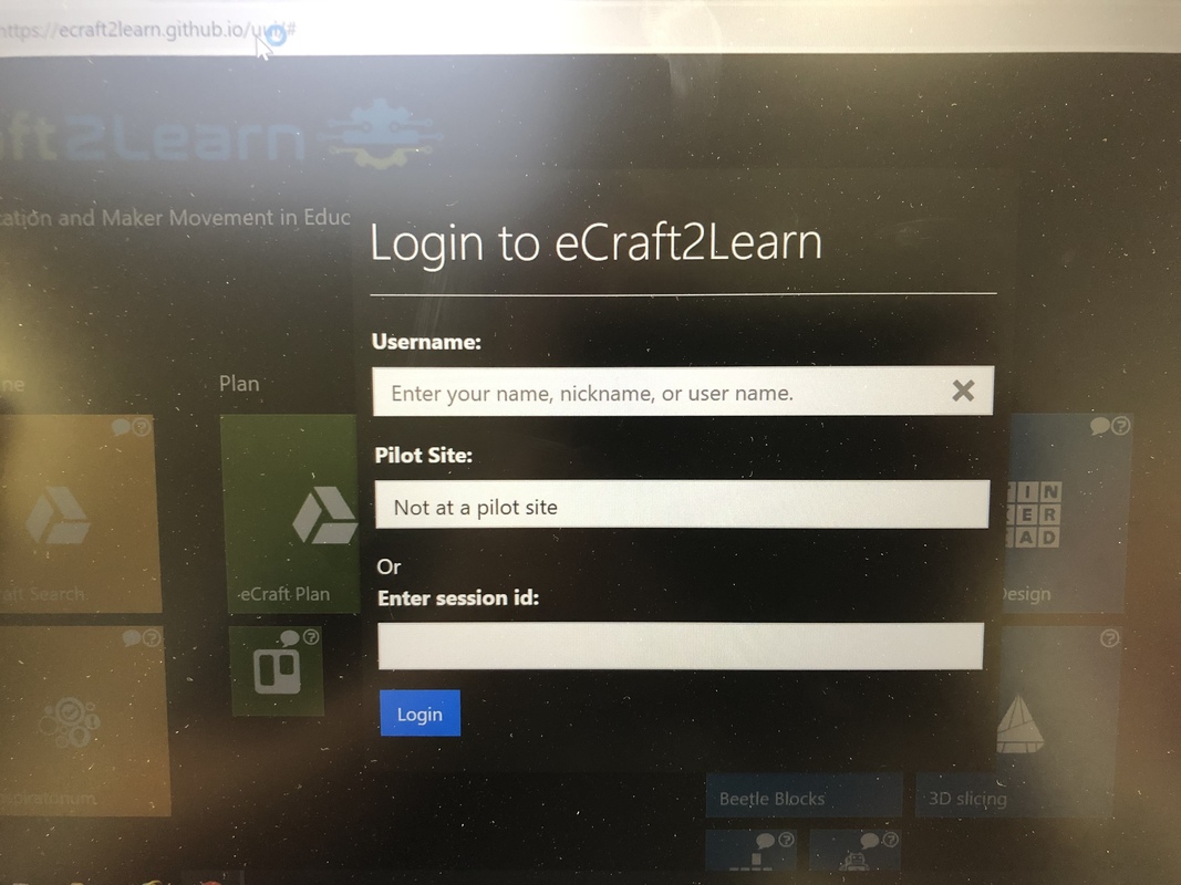
The Login is easy. You don’t register anywhere but still you make an account. So remember what you put as your username. You can continue your work from any computer with the same username.
TASK: give your team a name, then click ”Login”. (Leave others empty)
Now you can see the eCraft2Learn ecosystem. The five stages of eCraft2Learn are marked as their own sections. Notice from the screen:
1. Imagine
2. Plan
3. Create
4. Program
5. Share
There’s different kind of tools to every stages of work.

TASK: From ”Program” section, click ”Snap4Arduino”
https://ecraft2learn.github.io/uui/#

The Login is easy. You don’t register anywhere but still you make an account. So remember what you put as your username. You can continue your work from any computer with the same username.
TASK: give your team a name, then click ”Login”. (Leave others empty)
Now you can see the eCraft2Learn ecosystem. The five stages of eCraft2Learn are marked as their own sections. Notice from the screen:
1. Imagine
2. Plan
3. Create
4. Program
5. Share
There’s different kind of tools to every stages of work.

TASK: From ”Program” section, click ”Snap4Arduino”
Snap4Arduino: How it works and how to connect Arduino
Snap4Arduino is graphical programming environment wich works ”drag and drop”. It’s base on C++ programming language.
On the left corner of your screen you can see things like Motion, Looks, Control and so on. When you click any of them, there opens programming blocks. But before we program anything, we have to connect Arduino into Snap.
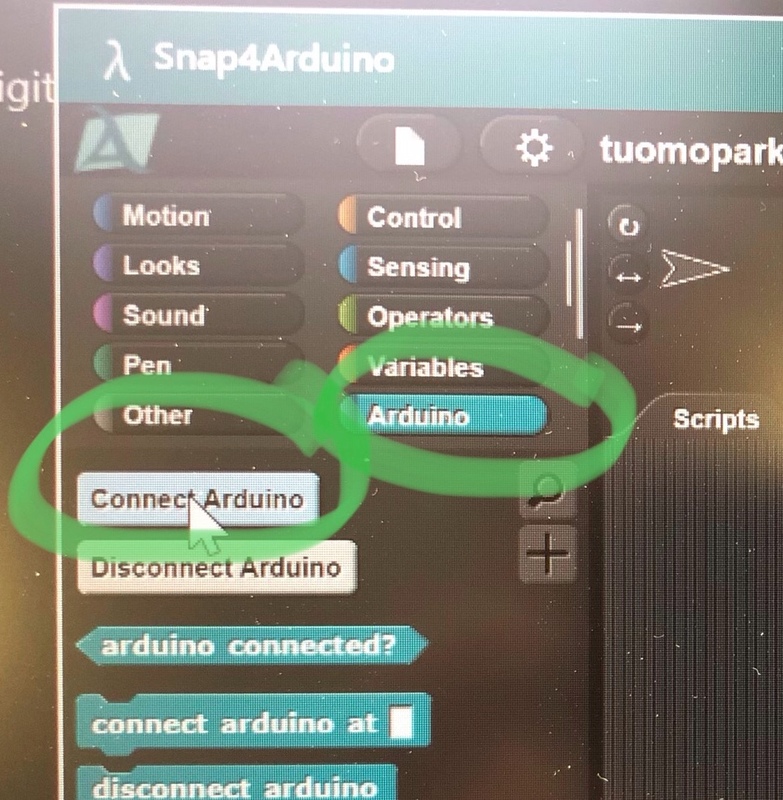
TASK: Choose ”Arduino” (picture above) and click ”Connect Arduino”. Then you see COM5, COM6 or dev0 whatever... Choose that what you see there.
If connection succeeded, you should see the text:

If not, please call your instructor 🤗
On the left corner of your screen you can see things like Motion, Looks, Control and so on. When you click any of them, there opens programming blocks. But before we program anything, we have to connect Arduino into Snap.

TASK: Choose ”Arduino” (picture above) and click ”Connect Arduino”. Then you see COM5, COM6 or dev0 whatever... Choose that what you see there.
If connection succeeded, you should see the text:

If not, please call your instructor 🤗
Snap4Arduino, Programming
God job, you are doing great! 🔥👍
Just to remember, this is what we have done:
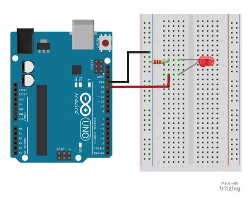
Now, we need to notice one very important thing from this: Where did you plug the wire in Arduino? If you did as the picture showed, you should have plugged in pin 13. If not, that’s ok too. The pin number is important. You’ll figure this out in one minute... :)
TASK: (pictures above) Choose ”Arduino” and from there ”Set digital pin...”, drag it into script area and drop it.
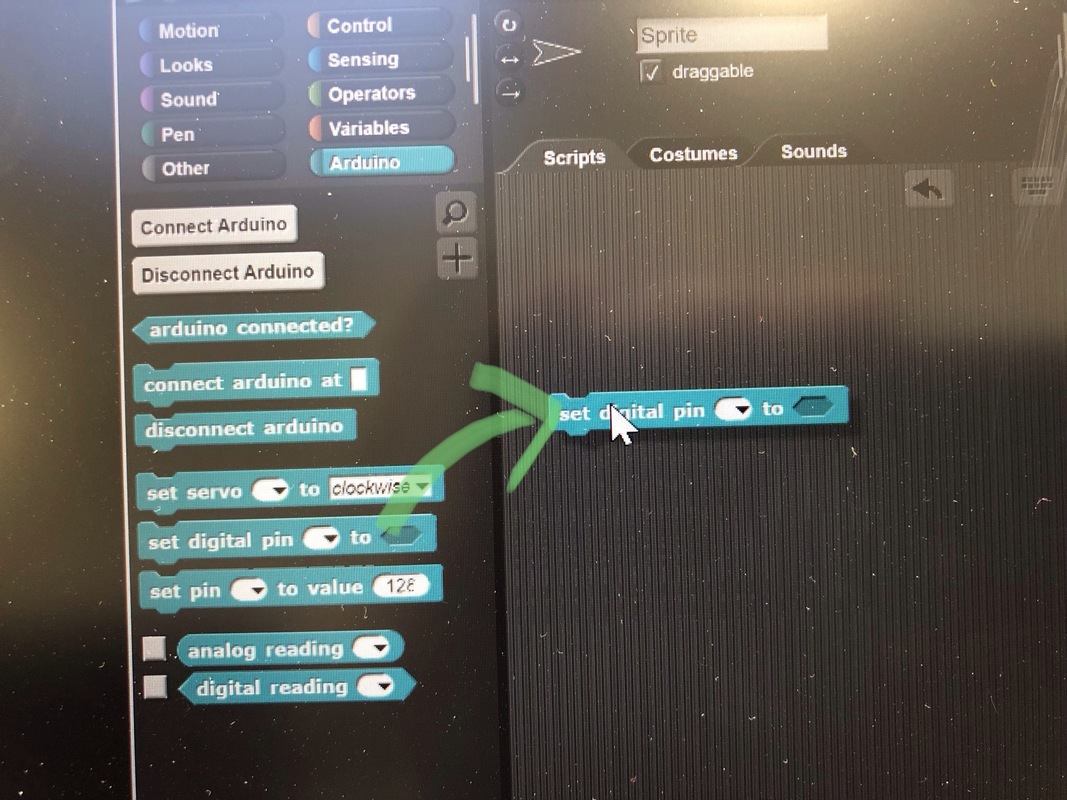
Now choose from drop-down menu your pin number, where you have connected the LED.
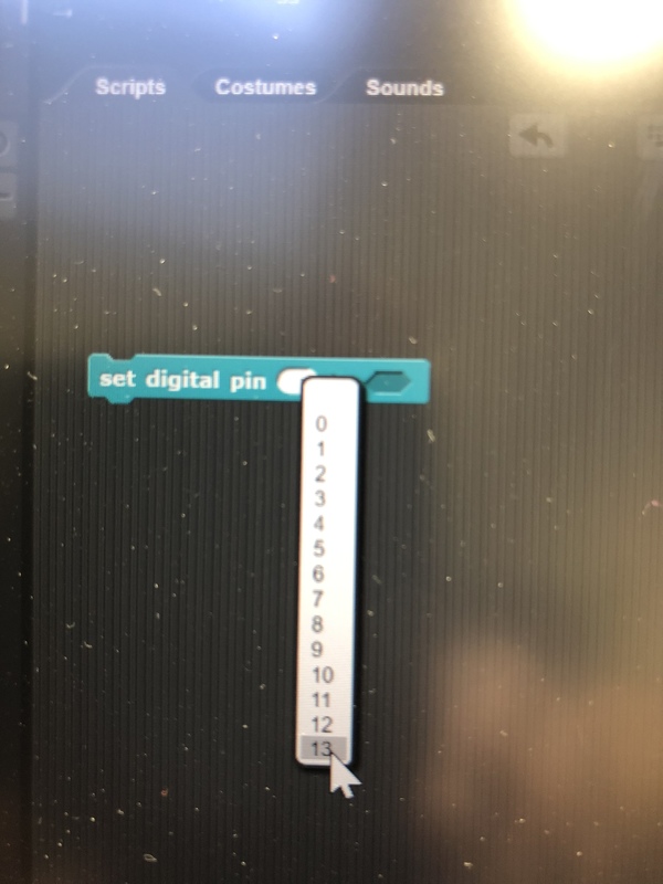
Now set electricity on into pin 13 with slide switch.

Click the yellow ”Control” and drag ”When clicked” block there, drop it and put in on top of ”Set digital pin” block.
Activate the code by clicking the block. The LED should have light now.
Just to remember, this is what we have done:

Now, we need to notice one very important thing from this: Where did you plug the wire in Arduino? If you did as the picture showed, you should have plugged in pin 13. If not, that’s ok too. The pin number is important. You’ll figure this out in one minute... :)
TASK: (pictures above) Choose ”Arduino” and from there ”Set digital pin...”, drag it into script area and drop it.

Now choose from drop-down menu your pin number, where you have connected the LED.

Now set electricity on into pin 13 with slide switch.

Click the yellow ”Control” and drag ”When clicked” block there, drop it and put in on top of ”Set digital pin” block.
Activate the code by clicking the block. The LED should have light now.
Snap4Arduino, a little more programming
Now, let’s get the LED blinking!
TASK: Do program below
1. Have another control block: ”Forever” and put it under ”when clicked”.
2. Move the ”Set digital pin” that you already have, inside ”forever”
3. Add Control block: ”wait 1 secs” under ”Set digital pin”
4. Click ”set digital pin” block with left mouse button —> ”Duplicate”. You should now get those two blocks.
5. Change the value of another ”Set digital pin” value to ”off” (click the slider).
Your program should look like this:

Click the ”When clicked” block and start the program. Change the values inside ”wait” block, for example 0.5 or 0.05.
Congratulations! Your first excercise is done! 🥳
TASK: Do program below
1. Have another control block: ”Forever” and put it under ”when clicked”.
2. Move the ”Set digital pin” that you already have, inside ”forever”
3. Add Control block: ”wait 1 secs” under ”Set digital pin”
4. Click ”set digital pin” block with left mouse button —> ”Duplicate”. You should now get those two blocks.
5. Change the value of another ”Set digital pin” value to ”off” (click the slider).
Your program should look like this:

Click the ”When clicked” block and start the program. Change the values inside ”wait” block, for example 0.5 or 0.05.
Congratulations! Your first excercise is done! 🥳
Short Mission: adapt your skills. The Joker!
Your task is to create ”the Joker” as seen on video below 🤡 Blinking eyes are important, the rest is up to you. You whatever material you find. But keep it simple.
Project lighthouse
Your task is to build a lighthouse / a beacon wich goes automaticly on when the sun sets and goes off when it’s bright. Ofcourse, the beacon is blinking. The Designis totally up to you! Use whatever material you can find in the Light a Bot. Hot glue guns, knives, paint, tape, etc etc are available!
Things that you need:
Arduino Uno + usb cable
LED
a resistor
a photoresistor
wires
Below you’ll find instructions how to wire a photoresistor and how to program it.
Put your team to work! Maybe you’ll draw a little plan? Do you want to do everything together? Or do you want to different tasks? Someone figuring out programming, someone getting material...However you do it, remember to co-operate and talk to each other!
If you use paint, try to do it in the beginning. The paint dries pretty fast, but can take 15-30 minutes.
Before you construct anything ”permanent”, you have to think what electronics is going to be there and how!
This is the last task at this work shop. We’ll leave about 20 minutes to your works presentations and general talk.
If, Else
In this tutorial, you can learn how to use a photoresistor as a sensor of light. There’s two leds. The other lits when it’s light, the other when it’s dark.
1. Install and wire two leds into your breadboard, as you installed on previous task. Use digital pins 11 and 13.
2. Here’s how to install a photoresistor:


- Above, I have made settings where digital pin 11 goes ”off” and pin 13 goes ”on” and the others are opposite. Those are inside a Control ”If Else” -block. There is a ”forewer” block waiting. Notice blocks colours. All control blocks are yellow.

- The program has to loop forever, because the photoresistor have to observe the amount of light all the time. So put you program inside ”Forever”

- I want to make it like this: If there is not enough light, turn pin 11 off and punt pin 13 on. Else turn on pin 11 and pin 13 off.
- The photoresistor is an analogic sensor. It gives values of the amount of light in numbers between 0-1023. The bigger number, more light.
- So, I’ll use the green ”smaller than” -block. I dropped it inside ”If”. But I’ll have to find out what numbers to put in. What is the amount of light now?

- Choose Arduino -blocks and pick ”Analog reading”. Now choose from dropdown menu the pin that you connected to Arduino. Now, click the block and you’ll see a number. Put you hand to shadow the photoresistor and click again. The numbers should change.
- In my opinion, 90 is a good value. If the sensors value is smaller than 90, I think it’s dark. You’ll have to test your suitable value and you can change it later.

- Now drag the ”Analog reading” inside the ”smaller than” -block, and write for example 90 on the other side. This means: ”if analog reading value is smaller than 90, turn pin 11 off and 13 on. Else...
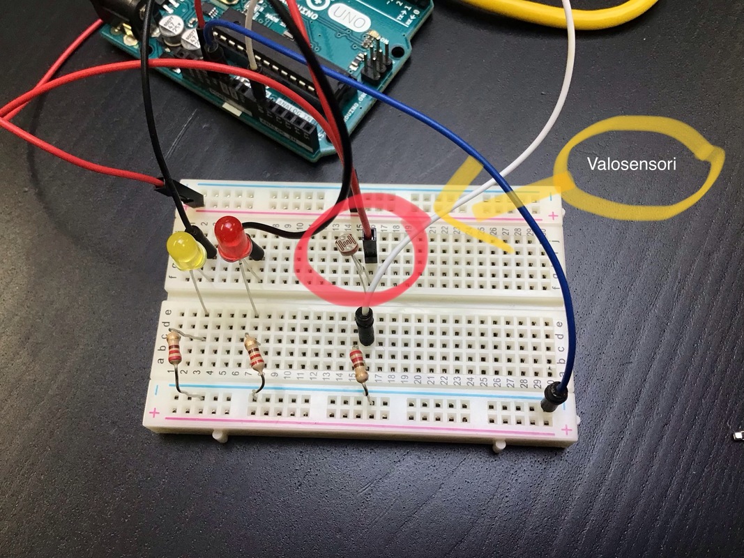
Here is a picture of components installed. Valosensori means photoresistor.
And, this seems to be working!
1. Install and wire two leds into your breadboard, as you installed on previous task. Use digital pins 11 and 13.
2. Here’s how to install a photoresistor:

Building the program

- Above, I have made settings where digital pin 11 goes ”off” and pin 13 goes ”on” and the others are opposite. Those are inside a Control ”If Else” -block. There is a ”forewer” block waiting. Notice blocks colours. All control blocks are yellow.

- The program has to loop forever, because the photoresistor have to observe the amount of light all the time. So put you program inside ”Forever”

- I want to make it like this: If there is not enough light, turn pin 11 off and punt pin 13 on. Else turn on pin 11 and pin 13 off.
- The photoresistor is an analogic sensor. It gives values of the amount of light in numbers between 0-1023. The bigger number, more light.
- So, I’ll use the green ”smaller than” -block. I dropped it inside ”If”. But I’ll have to find out what numbers to put in. What is the amount of light now?

- Choose Arduino -blocks and pick ”Analog reading”. Now choose from dropdown menu the pin that you connected to Arduino. Now, click the block and you’ll see a number. Put you hand to shadow the photoresistor and click again. The numbers should change.
- In my opinion, 90 is a good value. If the sensors value is smaller than 90, I think it’s dark. You’ll have to test your suitable value and you can change it later.

- Now drag the ”Analog reading” inside the ”smaller than” -block, and write for example 90 on the other side. This means: ”if analog reading value is smaller than 90, turn pin 11 off and 13 on. Else...
Here is a picture of components installed. Valosensori means photoresistor.

And, this seems to be working!