EEZYbotARM
Kaivuri testi neljällä moottorilla
#include <Servo.h> //Servo library
Servo servo_1; //initialize a servo object for the connected servo
Servo servo_2; //initialize a servo object for the connected servo
Servo servo_3; //initialize a servo object for the connected servo
Servo servo_4; //initialize a servo object for the connected servo
int angle1 = 0;
int angle2 = 0;
int angle3 = 0;
int angle4 = 0;
int potentio1 = A1; // initialize the A0analog pin for potentiometer
int potentio2 = A0; // initialize the A1analog pin for potentiometer
int potentio3 = A2; // initialize the A1analog pin for potentiometer
int potentio4 = A3; // initialize the A1analog pin for potentiometer
#define SERVO1PIN 7
#define SERVO2PIN 9
#define SERVO3PIN 10
#define SERVO4PIN 6
void setup()
{
servo_1.attach(SERVO1PIN); // attach the signal pin of servo to pin9 of arduino
servo_2.attach(SERVO2PIN); // attach the signal pin of servo to pin9 of arduino
servo_3.attach(SERVO3PIN); // attach the signal pin of servo to pin9 of arduino
servo_4.attach(SERVO4PIN); // attach the signal pin of servo to pin9 of arduino
}
void loop()
{
angle1 = analogRead(potentio1); // reading the potentiometer value between 0 and 1023
angle1 = map(angle1, 0, 1023, 60, 140); // scaling the potentiometer value to angle value for servo between 0 and 180)
servo_1.write(angle1); //command to rotate the servo to the specified angle
delay(5);
angle2 = analogRead(potentio2); // reading the potentiometer value between 0 and 1023
angle2 = map(angle2, 0, 1023, 0, 179); // scaling the potentiometer value to angle value for servo between 0 and 180)
servo_2.write(angle2); //command to rotate the servo to the specified angle
delay(5);
angle3 = analogRead(potentio3); // reading the potentiometer value between 0 and 1023
angle3 = map(angle3, 0, 1023, 30, 160); // scaling the potentiometer value to angle value for servo between 0 and 180)
servo_3.write(angle3); //command to rotate the servo to the specified angle
delay(5);
angle4 = analogRead(potentio4); // reading the potentiometer value between 0 and 1023
angle4 = map(angle4, 0, 1023, 30, 160); // scaling the potentiometer value to angle value for servo between 0 and 180)
servo_4.write(angle4); //command to rotate the servo to the specified angle
delay(5);
}
Oppiva robottikäsi
// Code written by Ryan Chan; it is pretty inefficient, but gets the job // done, I challenge you to make it more efficient!
//*IMPORTANT CHANGES IN VERSION 2: LEDs 4 and 5 have been moved to pins // 7 and 8 respectively; Buttons 1 and 2 have been moved to pins 12 and // 13 respectively. This is to make wiring easier.
#include <Servo.h>
Servo servo1; //Servos
Servo servo2;
Servo servo3;
const int LED1 = 2; //LEDs
const int LED2 = 3;
const int LED3 = 4;
const int LED4 = 7;
const int LED5 = 8;
const int button1 = 12; //Buttons
const int button2 = 13;
int button1Presses = 0; //Button values
boolean button2Pressed = false;
const int pot1 = A0; //Potentimeters
const int pot2 = A1;
const int pot3 = A2;
int pot1Val; //Potentimeter values
int pot2Val;
int pot3Val;
int pot1Angle;
int pot2Angle;
int pot3Angle;
int servo1PosSaves[] = {1,1,1,1,1}; //position saves
int servo2PosSaves[] = {1,1,1,1,1};
int servo3PosSaves[] = {1,1,1,1,1};
void setup() {
servo1.attach(7);
// Set up everything and will run once;
// attach servos and define the pin modes
servo2.attach(8);
servo3.attach(9);
pinMode(LED1, OUTPUT);
pinMode(LED2, OUTPUT);
pinMode(LED3, OUTPUT);
pinMode(LED4, OUTPUT);
pinMode(LED5, OUTPUT);
pinMode(button1, INPUT);
pinMode(button2, INPUT);
Serial.begin(9600);
}
void loop() {
// put your main code here, to run repeatedly:
pot1Val = analogRead(pot1);
// This will read the values from the potentimeters and store it...
pot1Angle = map(pot1Val, 0, 1023, 0, 179);
// ... and this will map the values from the potentiometers to
// values the servos can use and store it for later use
pot2Val = analogRead(pot2);
pot2Angle = map(pot2Val, 0, 1023, 0, 179);
pot3Val = analogRead(pot3);
pot3Angle = map(pot3Val, 0, 1023, 0, 179);
servo1.write(pot1Angle);
// These will make the servos move to the mapped angles
servo2.write(pot2Angle);
servo3.write(pot3Angle);
if(digitalRead(button1) == HIGH){
// This will check how many times button1 is pressed and save
// the positions to an array depending on how many times it is
// pressed; switch/case works like a if statement
button1Presses++;
switch(button1Presses){
case 1:
servo1PosSaves[0] = pot1Angle;
servo2PosSaves[0] = pot2Angle;
servo3PosSaves[0] = pot3Angle;
digitalWrite(LED1, HIGH);
Serial.println("Pos 1 Saved");
break;
case 2:
servo1PosSaves[1] = pot1Angle;
servo2PosSaves[1] = pot2Angle;
servo3PosSaves[1] = pot3Angle;
digitalWrite(LED2, HIGH);
Serial.println("Pos 2 Saved");
break;
case 3:
servo1PosSaves[2] = pot1Angle;
servo2PosSaves[2] = pot2Angle;
servo3PosSaves[2] = pot3Angle;
digitalWrite(LED3, HIGH);
Serial.println("Pos 3 Saved");
break;
case 4:
servo1PosSaves[3] = pot1Angle;
servo2PosSaves[3] = pot2Angle;
servo3PosSaves[3] = pot3Angle;
digitalWrite(LED4, HIGH);
Serial.println("Pos 4 Saved");
break;
case 5:
servo1PosSaves[4] = pot1Angle;
servo2PosSaves[4] = pot2Angle;
servo3PosSaves[4] = pot3Angle;
digitalWrite(LED5, HIGH);
Serial.println("Pos 5 Saved");
break;
}
}
if(digitalRead(button2) == HIGH){
// Pretty self-explnatory here
button2Pressed = true;
}
if(button2Pressed){
// if the boolean button2Press is true, then the servos
// will run though all their saved positionsfor(int i = 0; i < 5; i++){
servo1.write(servo1PosSaves[i]);
servo2.write(servo2PosSaves[i]);
servo3.write(servo3PosSaves[i]);
Serial.println(" potentimeter Angles: ");
Serial.println(servo1PosSaves[i]);
Serial.println(servo2PosSaves[i]);
Serial.println(servo3PosSaves[i]);
delay(1050);
}
}
delay(300);
}
Joystick Sensor Serial Read
TNG Robotics | www.tngrobotics.ca
Title | Joystick Sensor Serial Read
Connect | Servo to Arduino digital pin 5
Published | October 29, 2016
*/
const int VRx = 0; // Connect to Analog Pin 0
const int VRy = 1; // Connect to Analog Pin 1
const int SW = 4; // Connect to Digital Pin 4
void setup() {
pinMode(SW, INPUT);
digitalWrite(SW, HIGH);
Serial.begin(9600);
}
void loop() {
Serial.print("x-axis tilt: ");
Serial.println(analogRead(VRx));
Serial.print("y-axis tilt: ");
Serial.println(analogRead(VRy));
Serial.print("switch: ");
Serial.println(digitalRead(SW));
delay(800);
}
Testing the DC Motors 2
/**
* Bruno Santos, 2013
* feiticeir0@whatgeek.com.pt
* Small code to test DC motors - 2x with a L298 Dual H-Bridge Motor Driver
* Free to share
**/
//Testing the DC Motors
//Define Pins
//Motor A
int enableA = 10;
int pinA1 = 2;
int pinA2 = 3;
//Motor B
int enableB = 9;
int pinB1 = 4;
int pinB2 = 5;
//define time for run
// in milliseconds
int running = 10000; //10 secons
boolean play;
void setup() {
Serial.begin (9600);
//configure pin modes
pinMode (enableA, OUTPUT);
pinMode (pinA1, OUTPUT);
pinMode (pinA2, OUTPUT);
pinMode (enableB, OUTPUT);
pinMode (pinB1, OUTPUT);
pinMode (pinB2, OUTPUT);
play = true;
}
//motor functions
void motorAforward() {
digitalWrite (pinA1, HIGH);
digitalWrite (pinA2, LOW);
}
void motorBforward() {
digitalWrite (pinB1, LOW);
digitalWrite (pinB2, HIGH);
}
void motorAbackward() {
digitalWrite (pinA1, LOW);
digitalWrite (pinA2, HIGH);
}
void motorBbackward() {
digitalWrite (pinB1, HIGH);
digitalWrite (pinB2, LOW);
}
void motorAstop() {
digitalWrite (pinA1, HIGH);
digitalWrite (pinA2, HIGH);
}
void motorBstop() {
digitalWrite (pinB1, HIGH);
digitalWrite (pinB2, HIGH);
}
void motorAcoast() {
digitalWrite (pinA1, LOW);
digitalWrite (pinA2, LOW);
}
void motorBcoast() {
digitalWrite (pinB1, LOW);
digitalWrite (pinB2, LOW);
}
void motorAon() {
digitalWrite (enableA, HIGH);
}
void motorBon() {
digitalWrite (enableB, HIGH);
}
void motorAoff() {
digitalWrite (enableA, LOW);
}
void motorBoff() {
digitalWrite (enableB, LOW);
}
// Movement functions
void forward (int duration) {
motorAforward();
motorBforward();
delay (duration);
}
void backward (int duration) {
motorAbackward();
motorBbackward();
delay (duration);
}
void left (int duration) {
motorAbackward();
motorBforward();
delay (duration);
}
void right (int duration) {
motorAforward();
motorBbackward();
delay (duration);
}
void coast (int duration) {
motorAcoast();
motorBcoast();
delay (duration);
}
void breakRobot (int duration) {
motorAstop();
motorBstop();
delay (duration);
}
void disableMotors() {
motorAoff();
motorBoff();
}
void enableMotors() {
motorAon();
motorBon();
}
void loop() {
enableMotors();
while (play) {
//Forward for 1,5s
Serial.println ("forward...");
forward (1500);
//turn right
Serial.println ("right...");
right (500);
//Forward for 1,5s
Serial.println ("forward...");
forward (1500);
//turn left
Serial.println ("left...");
left (1000);
//Forward for 1,5s
Serial.println ("forward...");
forward (1500);
if (millis() > running) {
play = false;
Serial.println ("Falsing");
}
};
//disable motors
disableMotors();
}
Testing the DC Motors
* Bruno Santos, 2013
* feiticeir0@whatgeek.com.pt
* Small code to test DC motors - 2x with a L298 Dual H-Bridge Motor Driver
* Free to share
**/
//Testing the DC Motors
//Define Pins
//Motor A
int enableA = 10;
int pinA1 = 2;
int pinA2 = 3;
//Motor B
int enableB = 9;
int pinB1 = 4;
int pinB2 = 5;
void setup() {
Serial.begin (9600);
//configure pin modes
pinMode (enableA, OUTPUT);
pinMode (pinA1, OUTPUT);
pinMode (pinA2, OUTPUT);
pinMode (enableB, OUTPUT);
pinMode (pinB1, OUTPUT);
pinMode (pinB2, OUTPUT);
}
void loop() {
//enabling motor A
Serial.println ("Enabling Motor A");
digitalWrite (enableA, HIGH);
//do something
//forward
Serial.println ("Forward");
digitalWrite (pinA1, HIGH);
digitalWrite (pinA2, LOW);
//5s forward
delay (5000);
//reverse
digitalWrite (pinA1,LOW);
digitalWrite (pinA2,HIGH);
//5s backwards
delay (5000);
//stop
digitalWrite (enableA, LOW);
delay (5000);
//enabling motor B
//Since motor B is mounted reversed, PINs must be exchanged
Serial.println ("Enabling Motor A");
digitalWrite (enableB, HIGH);
//do something
//forward
Serial.println ("Forward");
digitalWrite (pinB1, LOW);
digitalWrite (pinB2, HIGH);
//5s forward
delay (5000);
//reverse
digitalWrite (pinB1,HIGH);
digitalWrite (pinB2,LOW);
//5s backwards
delay (5000);
//stop
digitalWrite (enableB, LOW);
delay (5000);
}
Kaivuri testi 4.ino
Servo servo_1; //initialize a servo object for the connected servo
Servo servo_2; //initialize a servo object for the connected servo
Servo servo_3; //initialize a servo object for the connected servo
int angle1 = 0;
int angle2 = 0;
int angle3 = 0;
int potentio1 = A1; // initialize the A0analog pin for potentiometer
int potentio2 = A0; // initialize the A1analog pin for potentiometer
int potentio3 = A2; // initialize the A1analog pin for potentiometer
int potentio4 = A3; // initialize the A1analog pin for potentiometer
#define SERVO1PIN 7
#define SERVO2PIN 9
#define SERVO3PIN 10
void setup()
{
servo_1.attach(SERVO1PIN); // attach the signal pin of servo to pin9 of arduino
servo_2.attach(SERVO2PIN); // attach the signal pin of servo to pin9 of arduino
servo_3.attach(SERVO3PIN); // attach the signal pin of servo to pin9 of arduino
}
void loop()
{
angle1 = analogRead(potentio1); // reading the potentiometer value between 0 and 1023
angle1 = map(angle1, 0, 1023, 60, 140); // scaling the potentiometer value to angle value for servo between 0 and 180)
servo_1.write(angle1); //command to rotate the servo to the specified angle
delay(5);
angle2 = analogRead(potentio2); // reading the potentiometer value between 0 and 1023
angle2 = map(angle2, 0, 1023, 0, 179); // scaling the potentiometer value to angle value for servo between 0 and 180)
servo_2.write(angle2); //command to rotate the servo to the specified angle
delay(5);
angle3 = analogRead(potentio3); // reading the potentiometer value between 0 and 1023
angle3 = map(angle3, 0, 1023, 30, 160); // scaling the potentiometer value to angle value for servo between 0 and 180)
servo_3.write(angle3); //command to rotate the servo to the specified angle
delay(5);
}
EEZYbotARM
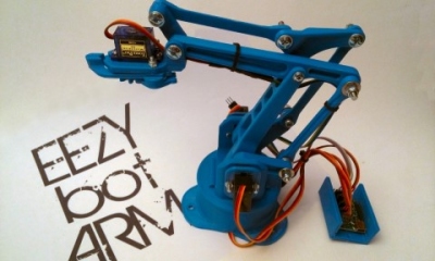
EEZYbotARM mk1

EEZYbotARM mk2